Experimenting with Keyboards
Keyboard preferences are very personal. Many people are satisfied with whatever keyboard they get when buying a laptop or computer, while some people prefer to heavily customise their typing experience. These days I seem to be in the latter group. While at university, I bought a mechanical keyboard, a Masterkeys Pro S, and used it as a prompt to re-learn to touch type “properly”. This led to me becoming frustrated with the way the rows of keys are staggered. Now that we don’t have mechanical linkages from each key to stamp letters onto paper, there’s no reason to keep using a layout that’s so unfriendly to our hands.
So what if we design the keyboard layout to align better to where your fingers go? A lot of companies have tried this - I’m not doing much that’s new. What I’ve ended up with is a completely custom keyboard designed and built from scratch. It’s still evolving, but at the moment it’s refined enough that I’ve been using it for the last couple of years. Read on to see the steps that got me to this point!
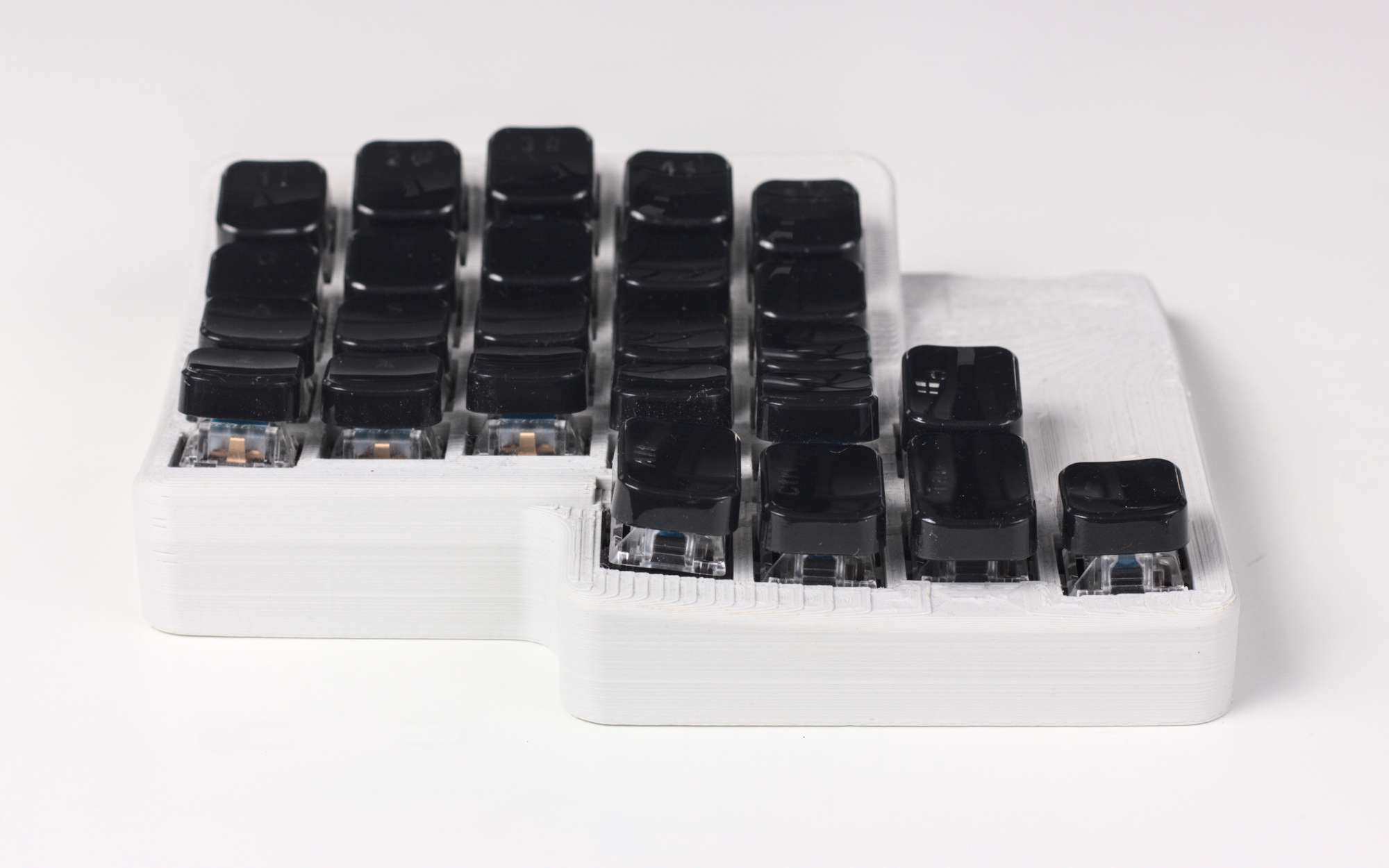
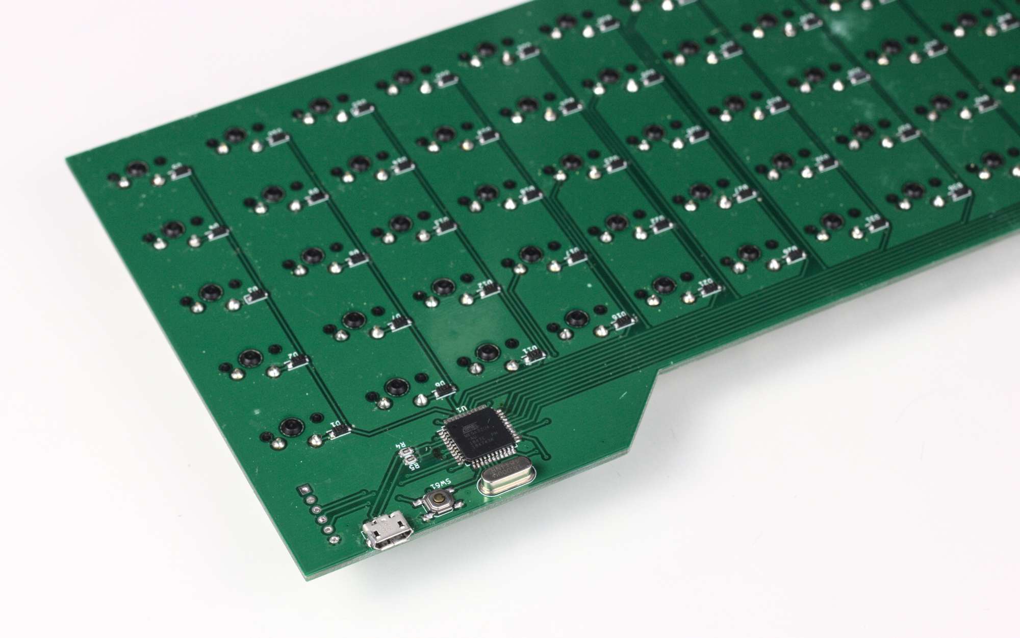
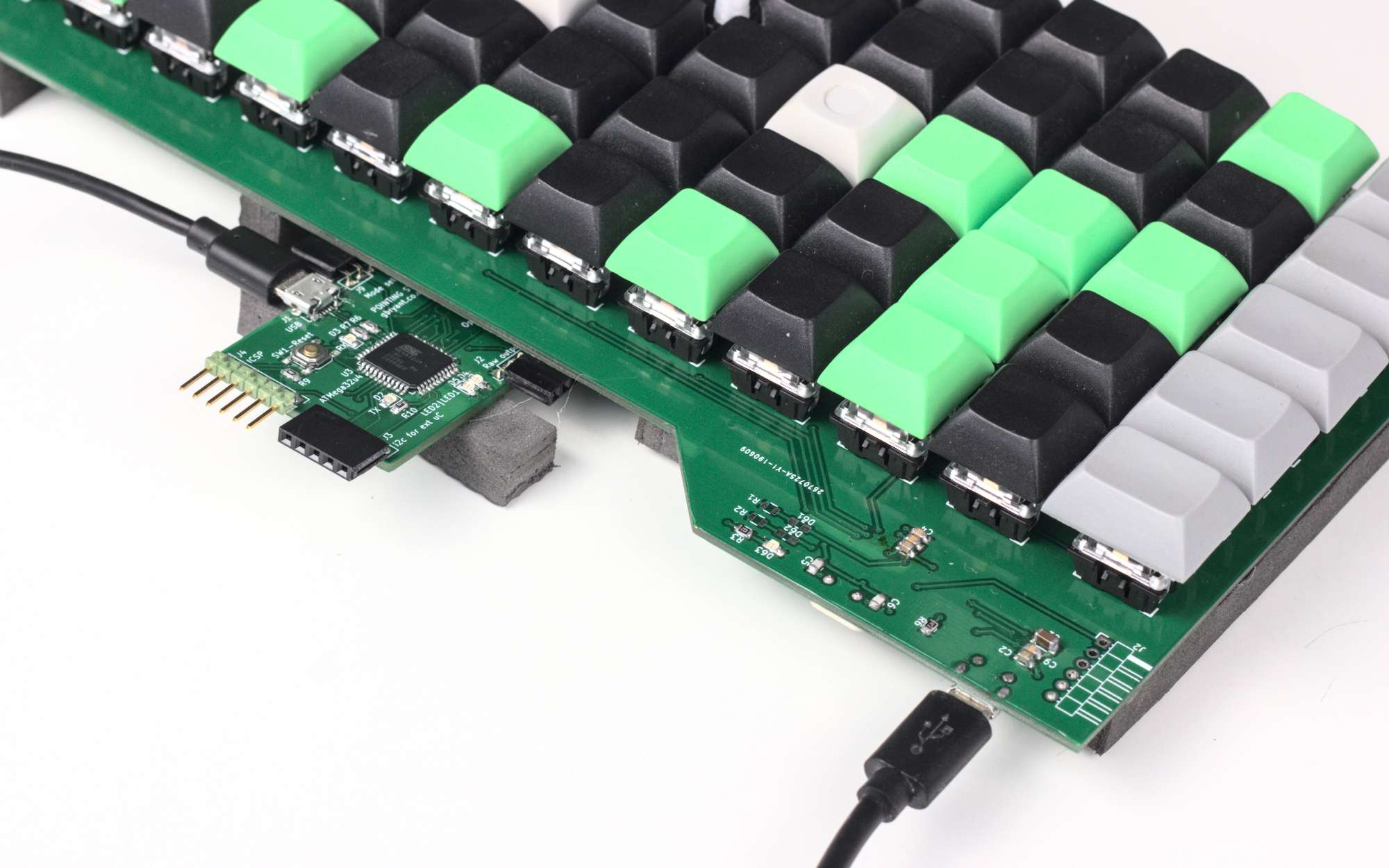
Split ergonomic keyboard
My first keyboard design was ambitious. Inspired by Atreus, Ergodox and Dactyl keyboards, my design is a split ergonomic keyboard. It has vertically staggered columns to match the resting positions of my fingers. The top is curved to mimic the arcs my fingers like to bend in (to a lesser extent than the Dactyl).
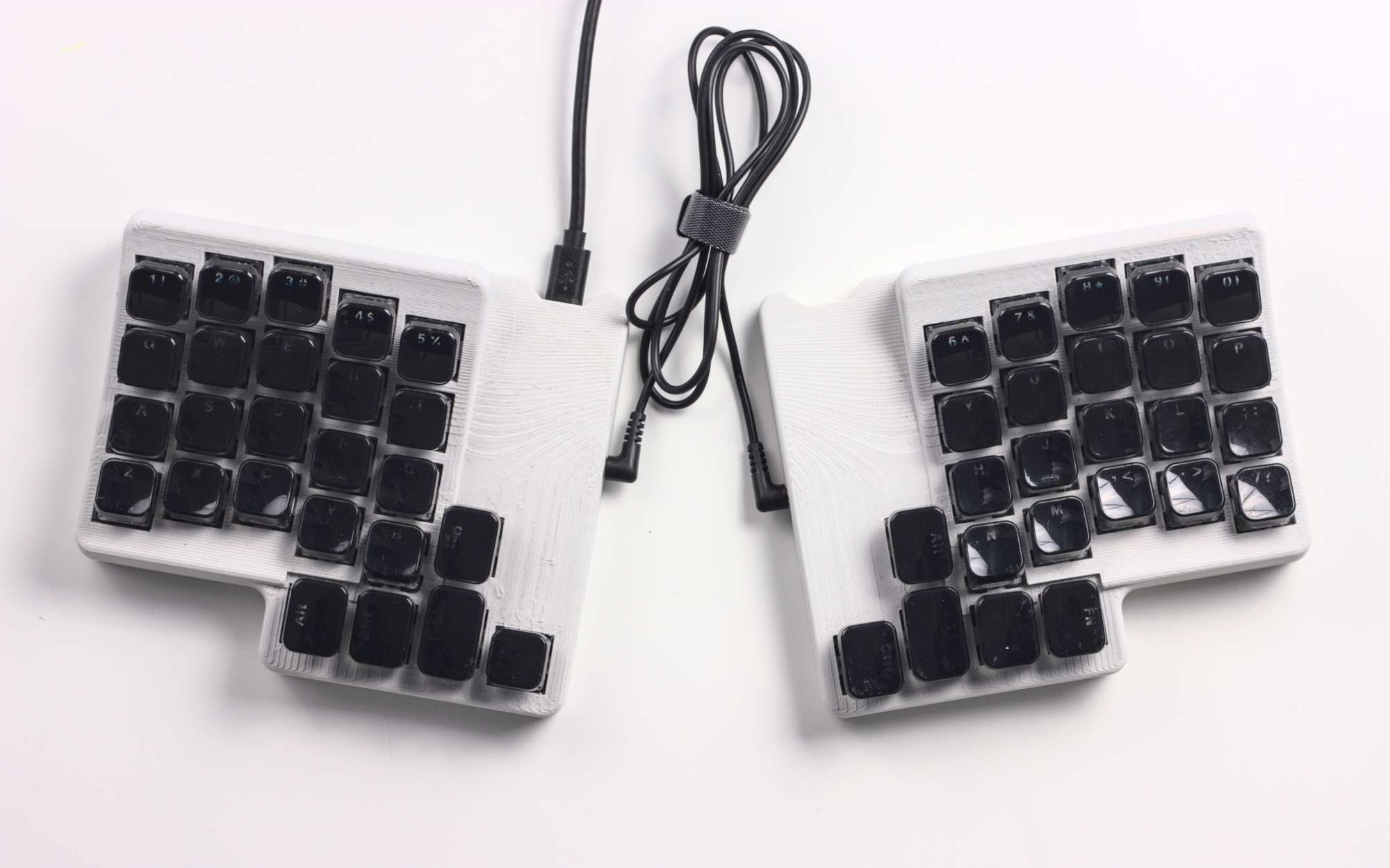
The design process started with some sketches and paper templates to figure out angles, curves and sizes. I assembled a flat version out of card to see if the thumb positions felt right relative to the finger keys. Getting the thumb positions to all feel good was quite tricky - there are positions that aren’t comfortable, like tucking your thumb right under your palm. Next I took to Rhino to design the keyboard properly in 3D. Using Rhino meant it’s a non-parametric surface model, which turned out to be a pain to modify later.
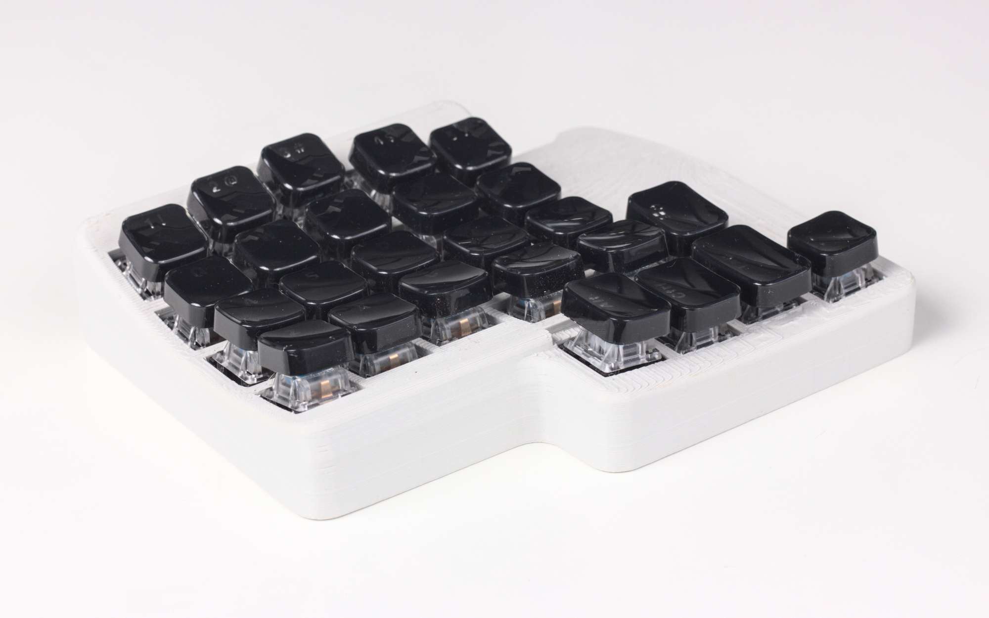
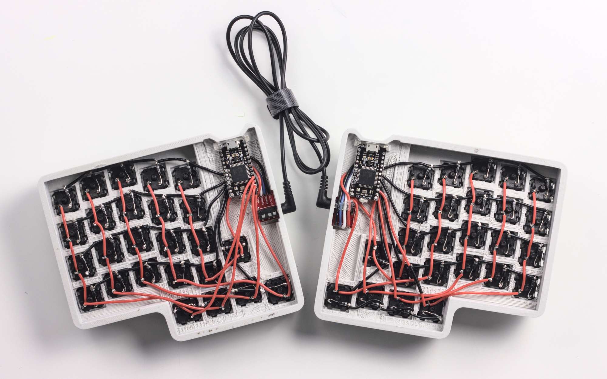
At maybe 10 hours, this was the longest 3D print I’d done at the time, but it went smoothly. Assembly was tricky too - the corner keys were tricky to solder without melting the case. But eventually I got it all together, figured out how to set up a new keyboard in QMK firmware and I was off!
After an initial period of figuring out a keymap that worked for me, it felt really nice to type on. The key switches I chose were Gateron Blues, which are satisfyingly clicky, but definitely on the loud side. The curve of the keys, while quite subtle, felt comfortable.
There were a couple of things I wasn’t a fan of: The keycaps were too flat and made it hard to position my fingers well on the keys; and I had trouble locating the right side of the keyboard. Splitting the keyboard didn’t work well for me - it turned out that I use my left hand as a reference for the keyboard’s position. When moving my hand back from the mouse, I had no idea where the right side of the keyboard was, because it wasn’t attached to the left side! Perhaps it was time to try making a non-split keyboard.
Handwired 12x5 ortholinear keyboard
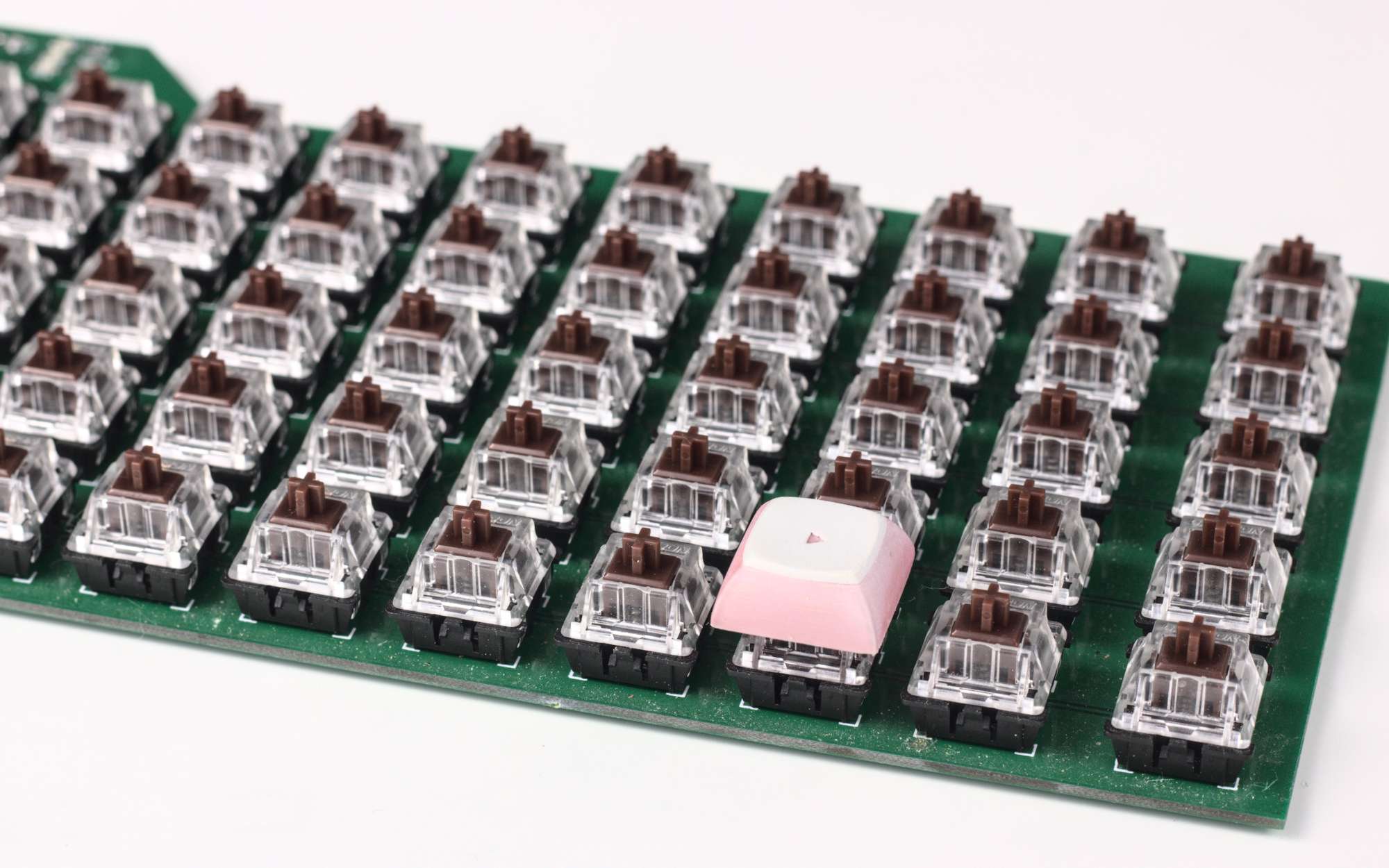
So how about something more conventional, but still without the typical staggered rows? An ortholinear keyboard (with keys aligned in a grid) seemed like a good bet. I’d been missing using my little finger for keys like Enter, Tab and Shift. Thumbs were fine for them, but it made it less familiar to use. It would be nice to have an extra column on either side for the modifier keys. I settled on a 12x5 grid layout, with slightly wider (1.25u) keys on the sides.
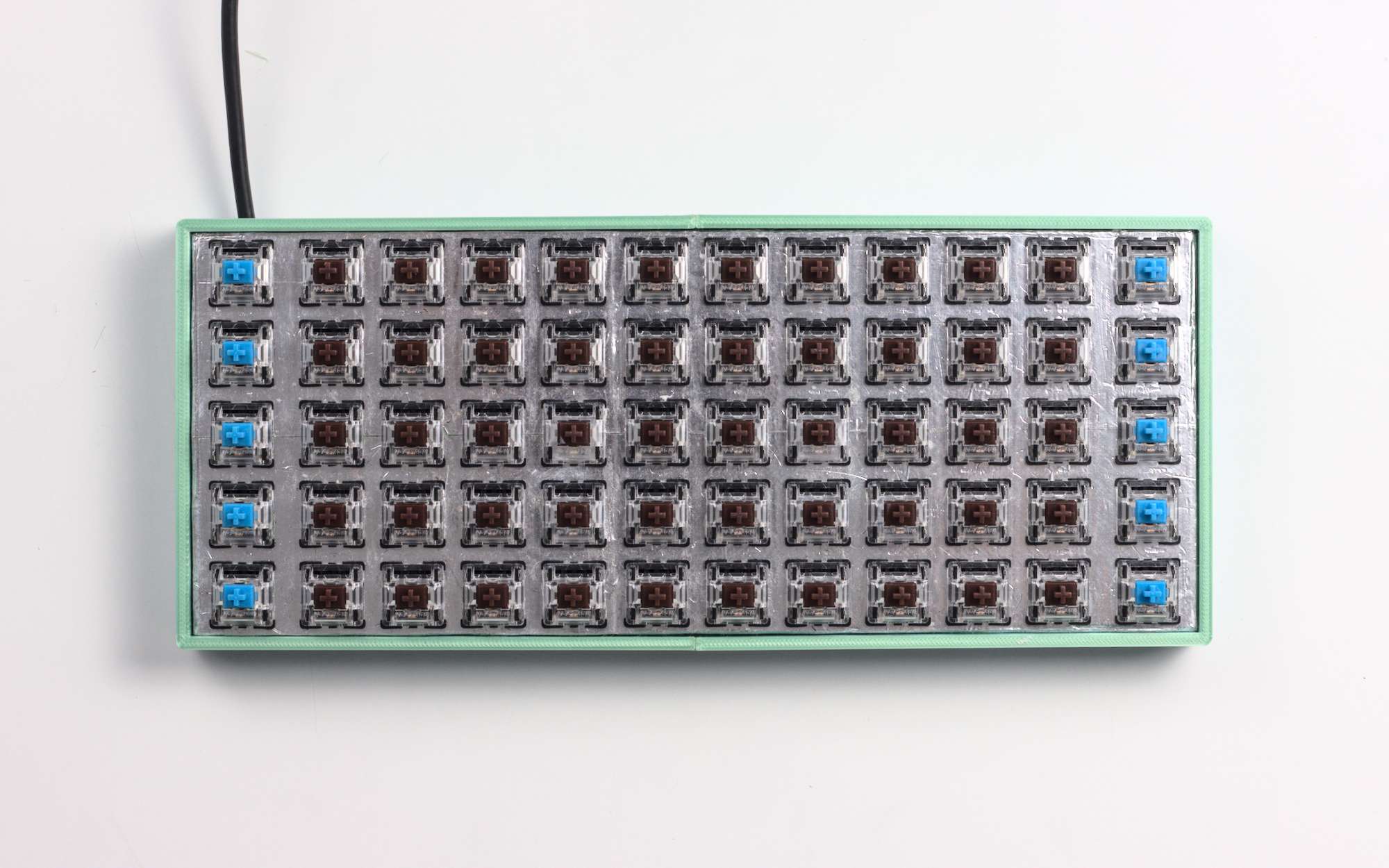
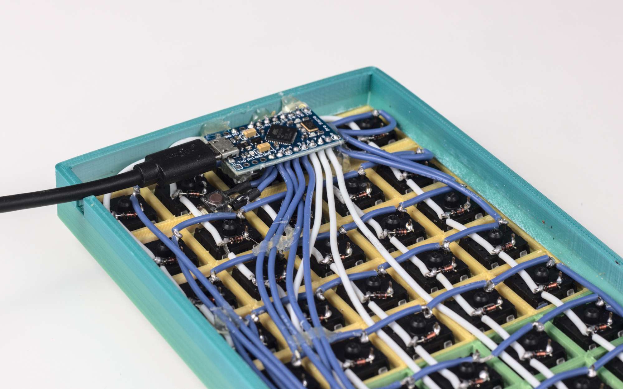
This was quite a rough prototype - the bottom is just filled with a foam pad to act as a cushioned foot. The Arduino Pro Micro is stuck in place with hot glue, and the case consists only of a plate for the keycaps and a supporting ring around the outside. Both parts of the case are split in half to fit on the bed of my 3D printer.
Despite that, I enjoyed using it a lot more - it felt quite familiar to use compared to the split keyboard. Unfortunately, both keyboards so far had intermittent solder joint issues. It seemed like they were getting fatigued from the constant typing. Either that or they weren’t good joints in the first place. It was pretty annoying to have to stop what I was doing to fix my keyboard.
Grid60
A more robust way to wire a keyboard would be to use a PCB, so I designed one. That way it’s at least a flat circuit that I’m more familiar with debugging. The key improvement was that it would make assembly much easier - no more twisting individual wires around each leg of each switch! I’d now be able to just solder the switches, diodes and microcontroller to the PCB.
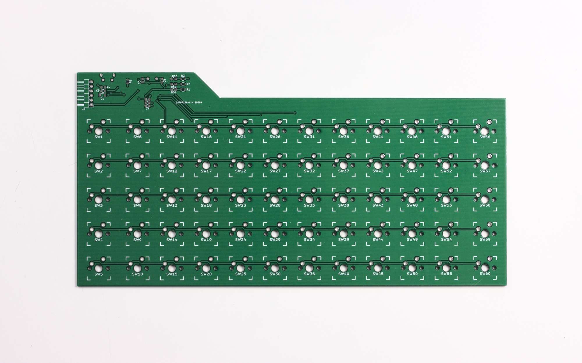

I also gave the project a name! Grid60 seems as good a name as any, since it has 60 keys arranged in a grid. Here’s the Git repo for version 1 of the PCB.
Basic version
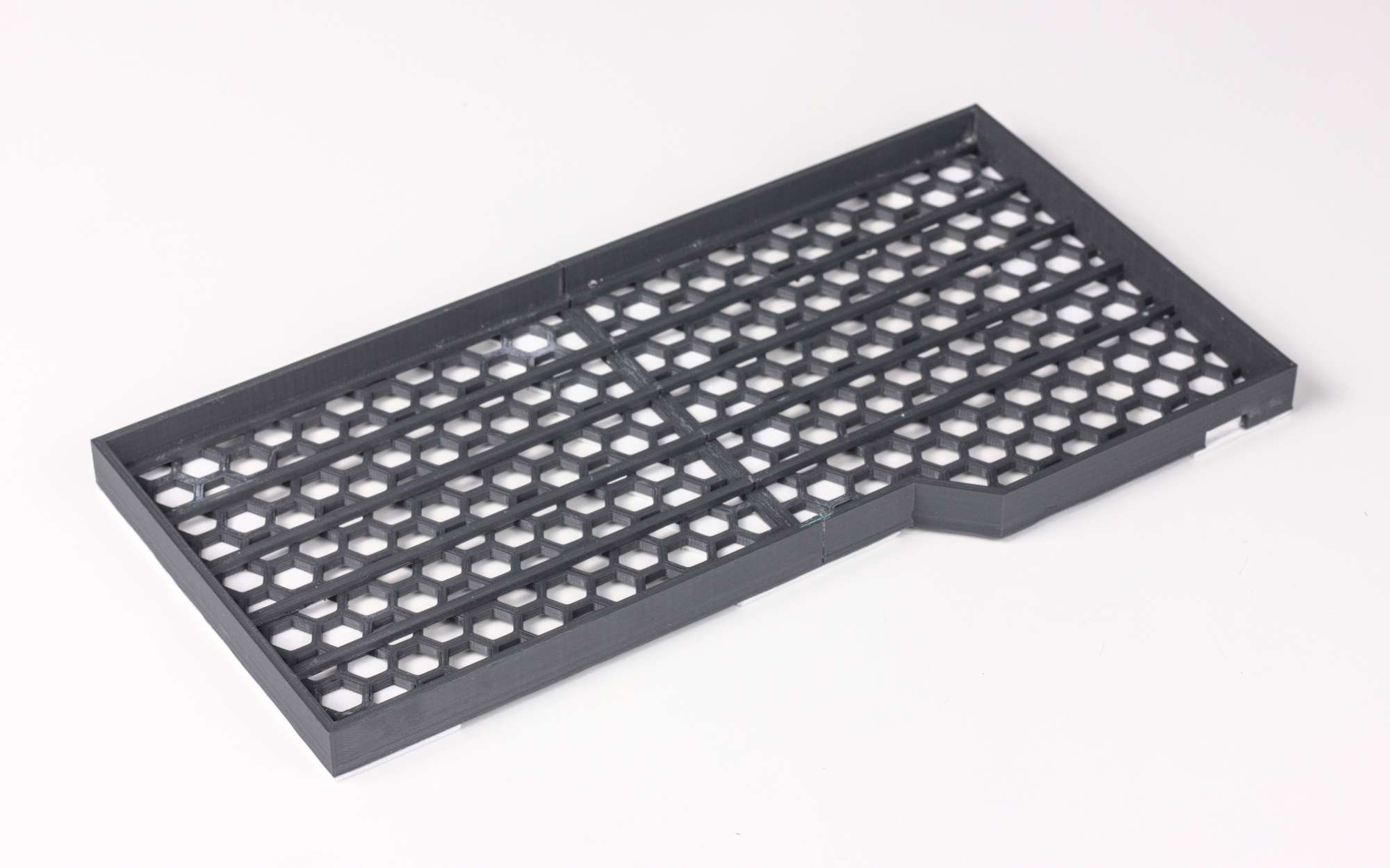
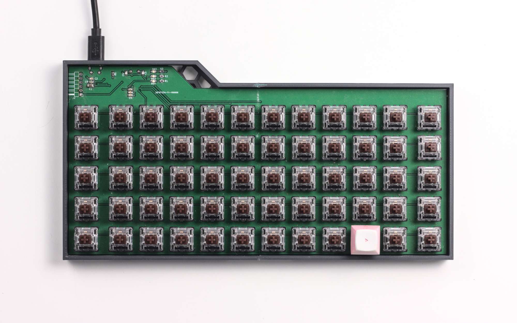
I threw together a quick base for the PCB in FreeCAD. Like all “temporary” solutions, I used it for a long time (about a year). The base is made of hexagons because I thought it looked cool, but it increased the print time a lot and you don’t really see it!
Designing a nicer case
Eventually I got fed up with the ugly case. I wanted to make something that felt a bit more like an actual product, particularly since I was using one of these in the office (back when that was a thing). Polishing 3D prints without painting them sounded like an interesting process, so I gave it a go.
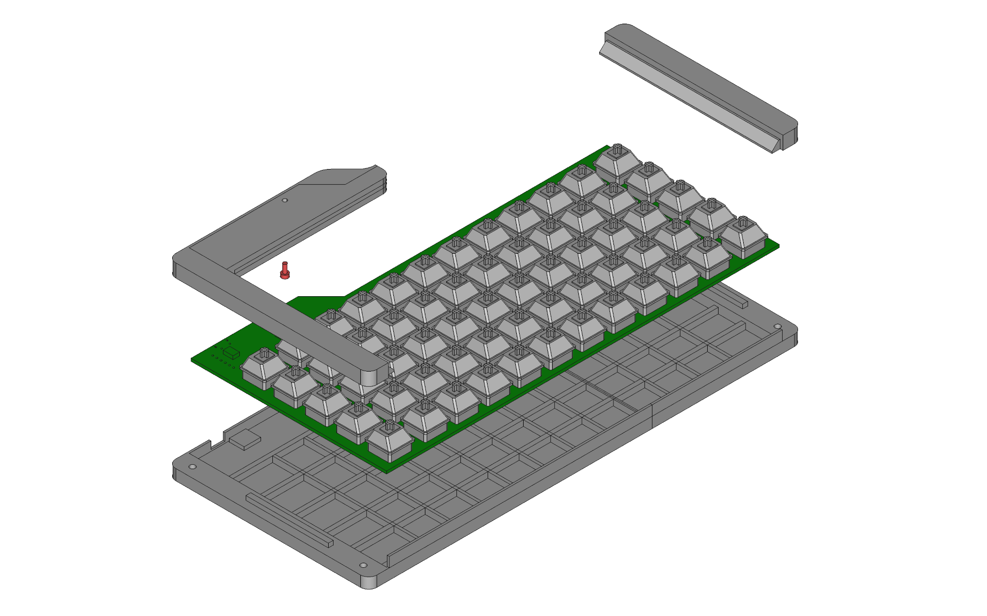
The design is split into top and bottom halves. In the first version, the top and bottom both covered the full width of the keyboard. This caused problems where the sanded and glued joint in the middle made the top and bottom different lengths. When they were joined together the keyboard bowed and twisted slightly! To fix it I split the top part into left and right pieces, so there’s no conflict between the lengths.
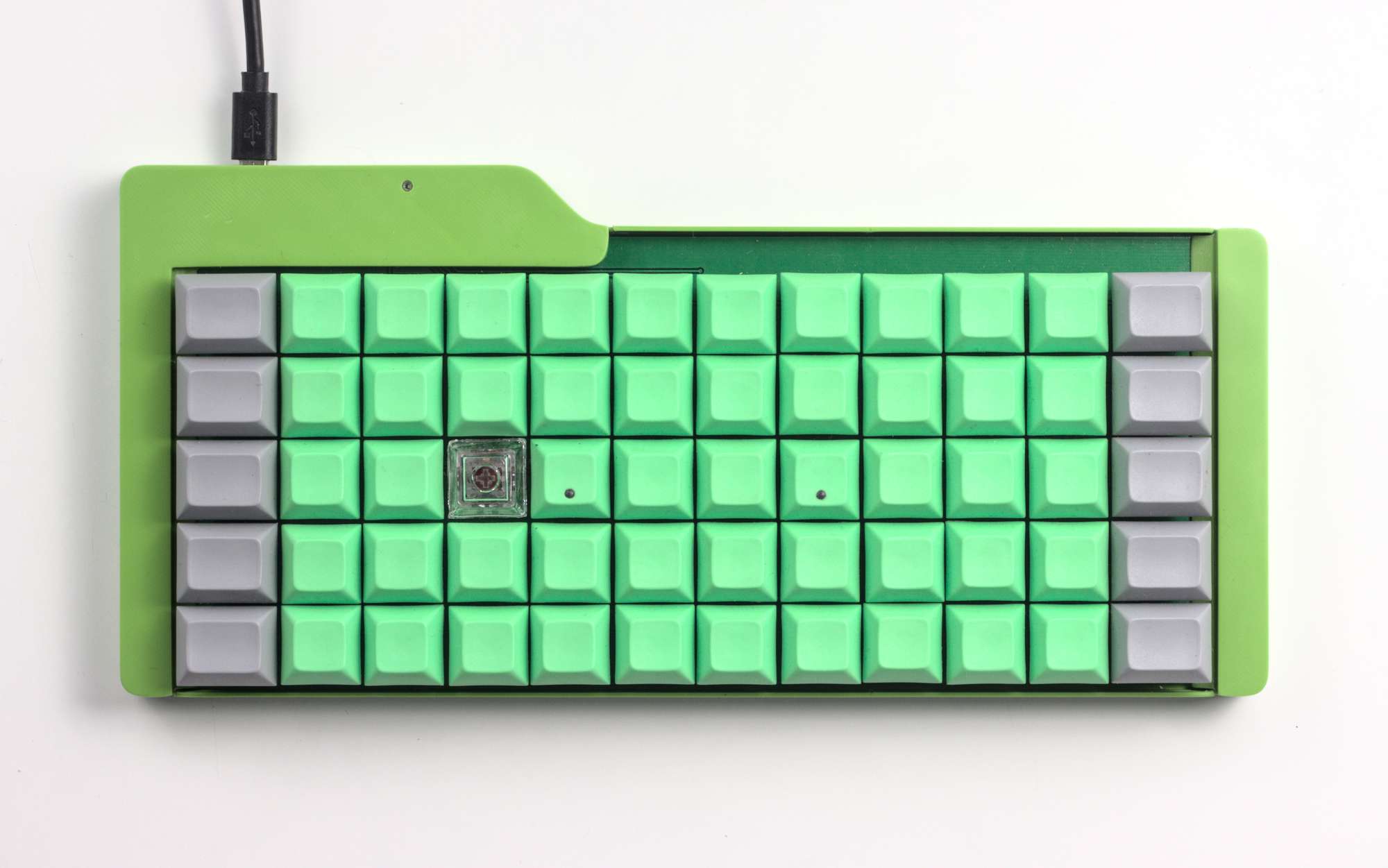
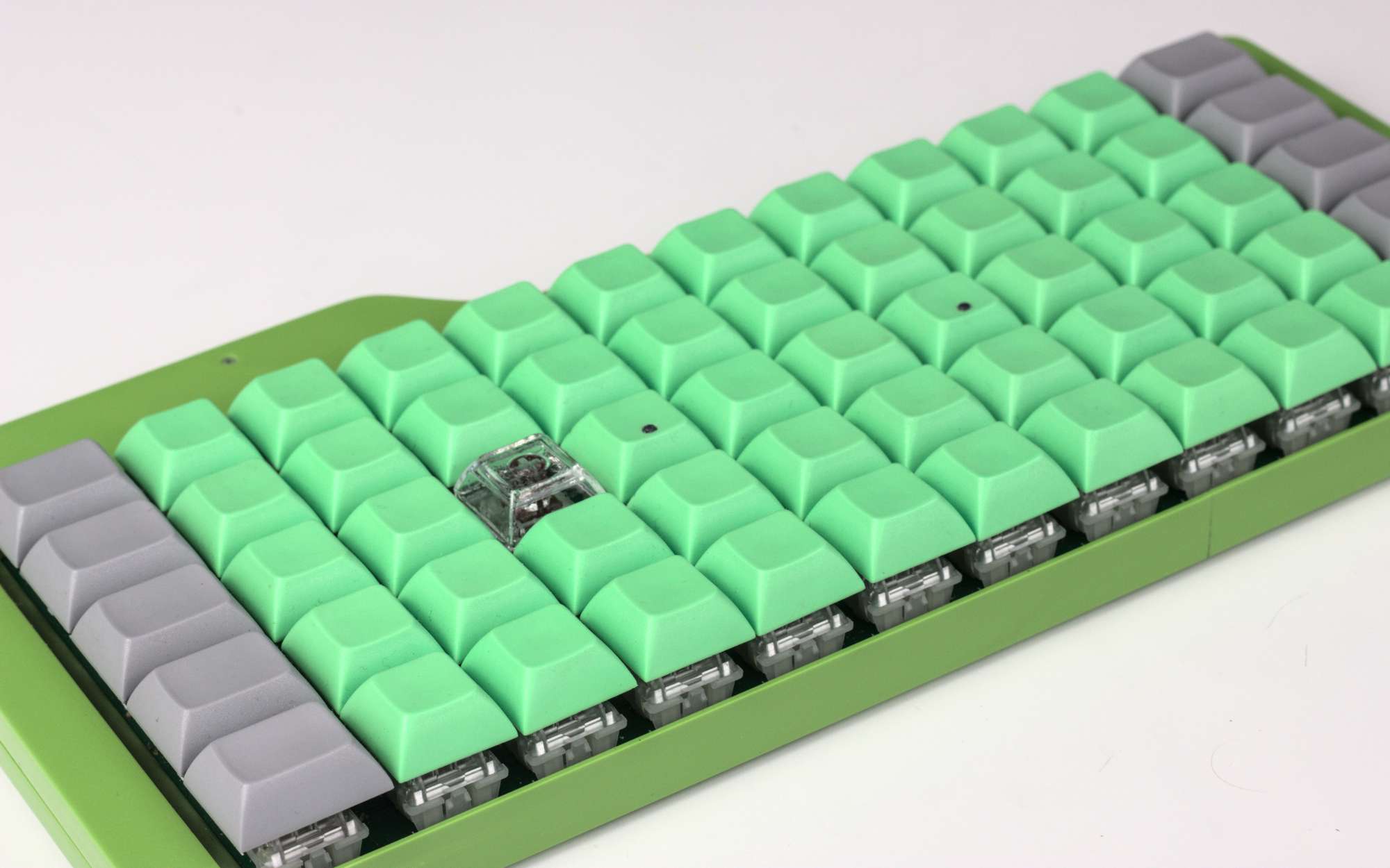
I’m really happy with how the case turned out - from a distance you could mistake it for an actual product! Close up it’s still clearly 3D printed but I’m ok with that. The glossy polished plastic feels really satisfying. There’s a little strip of the PCB you can see along the top edge, but rather than cover that up in future versions I’d just put some graphics on the PCB!
Adding a pointing stick
Pointing sticks are an input device you only rarely see, even on laptops. If you don’t recognise it from the generic name, they’re the red nub on ThinkPad keyboards, which is used like a joystick to control the mouse.
I’ve started developing my own pointing stick, with the aim to open-source it as a module that anyone can add to their keyboard designs. This sub-project deserves its own blog post, so details will have to wait. It’s still a work-in-progress, but the nub sits in the space between key rows and columns - between G and H in my layout.
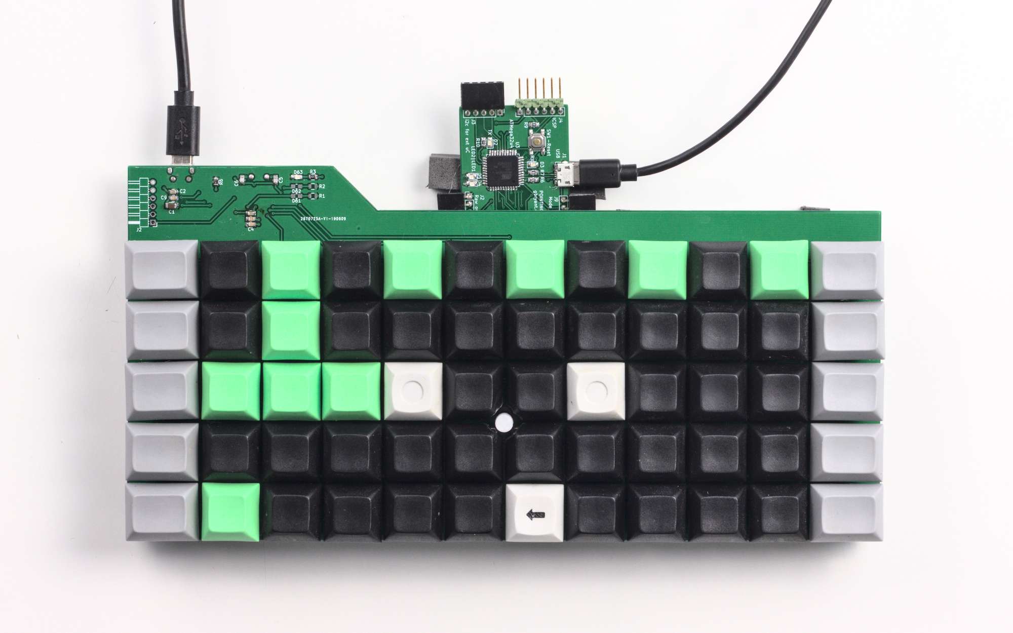
The pointing stick works like a tiny joystick, but with minimal movement. You move the nub (highly technical term), which is attached to a screw. The movement of the screw bends the pink cross-shaped mount on the bottom. The orange-brown strain gauges change resistance when the pink part bends, and the separate PCB amplifies and reads this signal. Unfortunately all this stuff adds quite a bit of height (~10mm) to the keyboard.
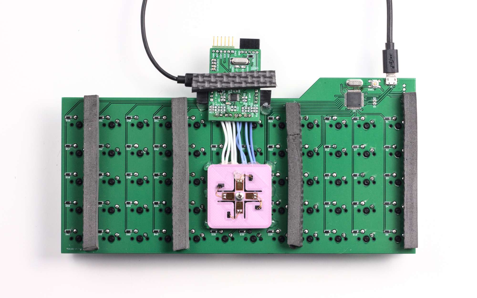
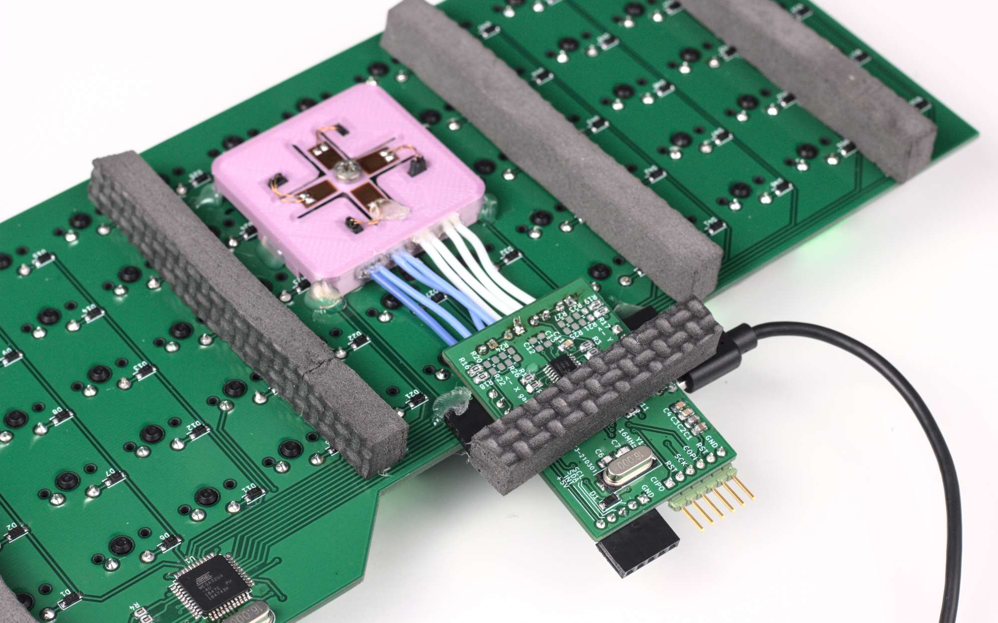
Right now the pointing stick presents itself to the computer as a separate USB mouse. The aim is to have it connected instead to the keyboard’s microcontroller over an i2c interface. Then it’s up to the keyboard to process the pointing stick input and send it to the PC. It could do things like have keys set up as mouse buttons, or keys that adjust settings on the pointing stick. It would be nice to integrate support for it into the QMK and/or ZMK keyboard firmwares.
You can find the files of the pointing stick project on my GitLab. There's also a blog post on the way with the "how"s and "why"s of the project.
Keymap
My keymap started off as a fairly conventional QWERTY layout. Of course, the grid60 has less keys than most. Some of the missing symbols got shifted onto a separate symbol layer, and I moved some utility keys onto another function layer. Over time I’ve added a few macros for common tasks.
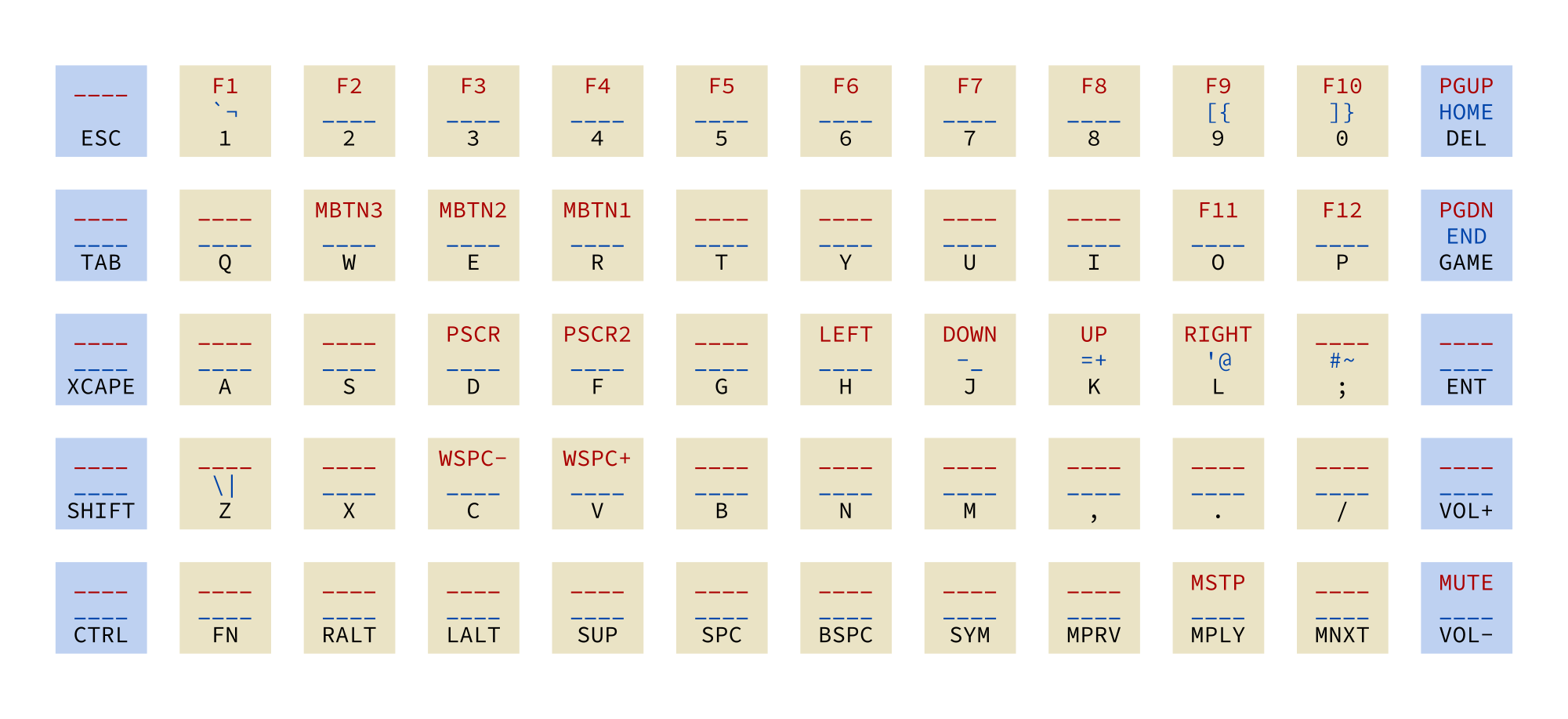
SYM or FN keys.
That sounds complicated to someone who’s not used to keyboard layers, but it feels very natural!
Here are the keys on the map that I think are noteworthy:
XCAPE: By default, justCtrl, but whenGAMEis tapped it switches to beingCtrlwhen held orEscwhen tapped. Quite nice for programming!MBTN(1/2/3): Mouse buttons, for use with the pointing stickPSCR2:Ctrl+Shift+Print screen- in GNOME this allows you to screenshot a regionWSPC(-/+): Change workspace - a macro forCtrl+Super+Left/Right arrowMPRV/MPLY/MNXT/MSTP: Music play controls
I also managed to add support for adjusting the keymap in VIA Configurator, although I wouldn’t recommend it if you’re building your own keyboard. The documentation seems to be limited to one guy’s livestreams, and the project is no longer open-source.
Keycap experiments
You may have noticed that most of the keycaps used on the prototypes are blank. That’s because keycap sets with legends are expensive! Especially so with odd requirements like 10 1.25-width keys. I quite like the shape of DSA caps, but it would be really nice to have custom legends on them to match my keyboard layout. To that end, I’ve tried out a couple of ways to make my own keycaps.
3D printing caps
It’s possible to print keycaps on a typical FDM 3D printer, but for a nice finish they need a lot of sanding. I found that some filaments worked better than others - one PLA split at the stem of every cap, while another worked perfectly. I found the slightly concave top very hard to sand without destroying the sandpaper. The sanding effort makes it unfeasible for a keyboard worth of labelled caps, but it’s still useful for a few customised ones, like my F and J keys with indents. So far I’ve managed to avoid buying a resin 3D printer!
Casting caps
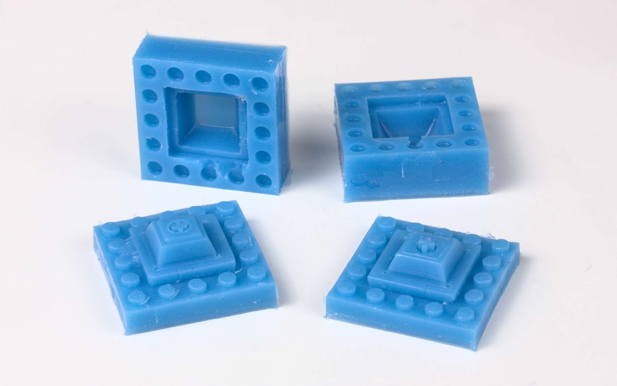
In theory I could 3D print the key shapes I need and then just cast them. It’s doesn’t help with getting a different legend for each key, but I tried it out anyway by making silicone moulds of 2 existing DSA keycaps.
The silicone mould making went well, but polyester resin wasn’t a good choice for casting them. It was brittle, quite soft and had a very strong styrene smell while casting. I wore a respirator and had good ventilation, but the smell still stuck around! I think the resin didn’t turn out very well because it was hard to accurately measure the very small quantity of catalyst required, even with precision scales. In future, I’ll try epoxy or polyurethane resin.
Conclusion
This has been quite a journey of experimentation. The split keyboard was a joy to type text on, but didn’t have quite enough keys for me to be comfortable programming (with the extra punctuation requirements). Designing it in Rhino meant that it was too daunting to make an updated version with changes, as did the hand-wiring. The various ortholinear keyboards feel great to type on and I’ve settled on a keymap that really works for me. I’m definitely interested in combining the two to make a small, ergonomic sculpted keyboard that’s not split.
I've made the case design, keycap ideas, PCB design and firmware for the grid60 available on GitLab. Here's a link to the repo!
As for the pointing stick, we’ll just have to wait and see…